- CYPE >
- english >
- new features >
- 2012 >
- CYPECAD
The 2012 version of CYPECAD incorporates the following new features.
Detailed reports on the ultimate limit state checks of concrete columns in CYPECAD's new column editor
New for the 2012 version, is CYPECAD’s column reinforcement editor which displays all the information related with their design, including the generation of detailed ultimate limit state (U.L.S.) reports. This new tool will be available in an update patch after 2012.a for use with the Spanish EHE-08 concrete code and in subsequent patches for other concrete codes.
The programs CYPECAD, Metal 3D and Portal Frame Generator already allowed for, as of previous versions, to obtain detailed ultimate limit state (U.L.S.) reports for rolled, welded and cold-formed steel, aluminium and timber.
Ultimate limit state check reports of concrete columns
These reports contain all the checks carried out by the program when designing reinforced concrete columns, and so constitute an important document with which the user can:
- Verify and justify the design of concrete columns. The user can examine, on a one-to-one basis, all the checks carried out by the program to check the concrete section and calculate the longitudinal and transverse reinforcement.
- Optimise the design of the concrete columns. By observing the checks that are not met, it is easier to decide which is the optimum solution to resolve the problem (increase the concrete section, the longitudinal reinforcement, or the transverse reinforcement, etc.). Similarly, if all the checks are met, these reports contribute on decision making so to obtain a better usage coefficient of the columns.
The level of detail of these reports also serves as a reference to the user to know all the checks a concrete column is subject to. The concrete does not limit itself to indicate whether or not the column fails or passes the checks, but indicated which specific checks it fails. Additionally, each check refers to the code and article stating the requirements.
CYPECAD, Metal 3D and the Portal Frame Generator also provide detailed U.L.S. reports for rolled, welded and cold-formed steel elements.
CYPECAD's new column editor offers extensive and thorough information on the data, checks, design and results of all the concrete and steel columns of the job. It is activated by selecting any column using the option Columns > Edit from the Results tab.
Within the column editor of CYPECAD, there are four sections where the following information can be visualised:
- Column groups
List of all the column groups - Columns on floor
Column distribution on plan - Reinforcement edition
Edition of the reinforcement by floor of the column in the Column groups section - Check summary
Worst case forces of the column of the floor selected in the Column groups and Column reinforcement sections; general usage coefficients and all the checks which have been carried out.
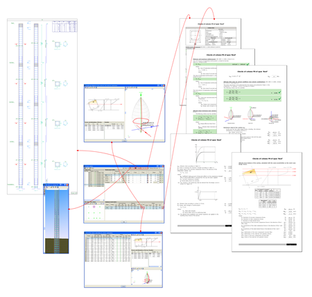
In the previous image, the detailed information provided by CYPECAD's column editor can be seen:
- Equilibrium results
Where the stress-deformation graphs are represented and the capacity volume of the concrete section. - Force combinations
- Ultimate limit state check report of the selected column span
- Ultimate limit state check report of the selected column
- 3D view of the column reinforcement
- Details of the column reinforcement
Automatic generation of column reinforcement tables
CYPECAD will incorporate in a patch after the 2012.a version (together with the new column editor and detailed ultimate limit state reports) the automatic generation of the column reinforcement tables to analyse with the Spanish EHE-08 code. It will then be implemented for other concrete codes.
This automatic generating feature is a great tool for users who wish to use personalised reinforcement tables, as they will save time not having to undergo any laborious tasks, and with the guarantee that the reinforcement table generated by CYPECAD is coherent and responds to their expectations. Additionally, users who in previous versions rejected the idea of creating their own column reinforcement tables due to the complexity of the process, can personalise them easily.
The automatic generation of the column reinforcement tables can be configured and the user can select the usable diameters, activate and calibrate various options regarding the configuration of the longitudinal reinforcement and stirrups. The following images display all the configuration options for the generation of the column reinforcement tables.
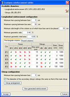

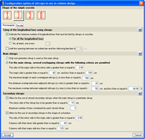
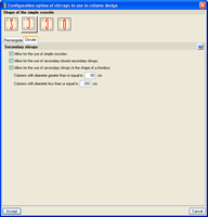
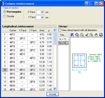 In the first two dialogues displayed, a button is present to visualise the reinforcement tables that are generated with the selected options.
It is important to note that the reinforcement arrangements indicated by the selected code prevail in case there is any conflict with the options configured by the user.
Elimination of the rigid diaphragm assumption of walls and beams not connected to floor slabs
As of the 2012.a version, CYPECAD automatically eliminates the rigid diaphragm assumption at floor level in wall spans that do not come into contact with any floor slabs.
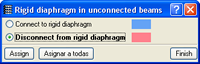
In the case of beams that are not in contact with floor slabs, the elimination of the rigid diaphragm is optional (Beams/Walls in the Beam Definition tab > Rigid diaphragm in unconnected beams) and the user can deactivate the rigid diaphragm assumption if the beam is to be designed to resist the forces that could affect it in its horizontal plane. The longitudinal reinforcement of the beams for which the rigid diaphragm assumption is freed is laid as continuous.
So to remove any chance of confusion, the program only allows for unconnected beams to be exempt from the rigid diaphragm.
Collective protection systems in CYPECAD
The new module Collective protection systems generates the drawings of the collective protection systems of a job in CYPECAD.
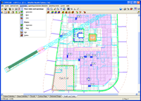
The 2012.a version of CYPECAD includes an extra tab at the bottom of the screen. Along with the other five tabs (Column Definition, Beam Definition, Results, Contour Maps and Deformed Shape), the Health and Safety tab has been implemented. Upon clicking on it, the user can include the following elements by selecting them from the top menus:
- System V vertical safety nets
- Guardrails
- Opening protection elements
- Stacking zones
- Cranes
More information on this new CYPECAD module can be found in the Collective protection systems page.
New codes for the Joints modules
The following rolled steel codes have been implemented for the five joints modules (Joints I, Joints II, Joints III, Joints IV and Joints V):
- ANSI/AISC 360-05 (LRFD) (USA – International )
- IS 800: 2007 (India)
- New modules and programs
- Collective protection systems (CYPECAD, as of the 2012.a version)
- Plane stress walls (CYPECAD, as of the 2012.h version)
- New features and improvements
Tel. USA (+1) 202 569 8902 // UK (+44) 20 3608 1448 // Spain (+34) 965 922 550 - Fax (+34) 965 124 950