- CYPE >
- english >
- new features >
- 2012 >
- metal 3d
Metal 3D and the Integrated 3D structures of CYPECAD have the following new features.
- New features for aluminium sections (as of the 2012.a version)
- Automatic calculation of the susceptibility to local buckling due to compression
- Heat affected zones
- Improvements in the design of special aluminium sections
- IFC file import (as of the 2012.b version)
- New codes for the Joints modules (as of the 2012.a version)
- New types of joints for the Joints V module (as of the 2012.b version)
- More new features
New features for aluminium sections (as of the 2012.a version)
Automatic calculation of the susceptibility to local buckling due to compression
In previous versions of the program, the automatic calculation of the susceptibility to local buckling due to compression was already included assuming that each of the flat elements making up the section buckled in an isolated manner (independent from the rest), and the possibility was included, for any other type of buckling other than the individual type to be considered, to modify the local buckling coefficient which affects the slenderness parameter associated to each element. In this new version, the automatic calculation of the susceptibility to local buckling due to compression considering the possibility that several elements can buckle together as if they were a single element, is also included, hence combined buckling modes are obtained. The program is able to detect and analyse the buckling in a group of elements in the following cases:
- Element sequence with all their ends aligned along a straight line
- Element sequence with all their ends arranged along a circumference arc with small curvature
- Element sequence making up a cell
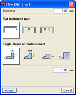
The combined buckling is also studied if the elements making up the section have been stiffened, which is commonly referred to as buckling due to distortion. Regarding the stiffened elements, a new assistant has been implemented for the design with standard reinforcement in accordance with that exposed in EC9.
In this new version, aluminium sections requiring longitudinal welds can now be introduced in the Special aluminium sections editor. The program checks these sections taking into account the reduction of the resistance properties which arise in areas close to these welds: where the elastic limit of the material is affected significantly. The softened zone is referred to as the HAZ (heat affected zone), its extent and severity are calculated by the program.
Improvements in the design of special aluminium sections
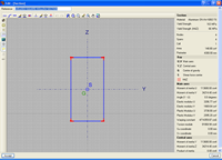
The design process of special aluminium sections has been optimised by now obtaining the shear plastic areas, as well as the reductions which, because of the tangential stresses due to the torsional moment and shear forces, arise when subject to normal forces: axial force and bending moments. This way, in checks where in previous versions, an elastic analysis was used (in accordance with the plastification criteria exposed in EC9), now a plastic analysis is carried out and, therefore, improved usage factors are obtained.
IFC file import (as of the 2012.b version)
Metal 3D now allows for structural analysis models to be imported from IFC files. IFC files which only contain the physical model and not the structural analysis model, do not contain any information which Metal 3D can read.
In IFC format files, the structural analysis model is composed of structural type entities, such as nodes, bars, loads, etc. Additionally, the relationship between nodes and bars is defined in an explicit way by means of fixity conditions. It is similar to the model a user would define in Metal 3D.
The entities Metal 3D currently imports from the IFC files are the following:
- Nodes (IFCStructuralPointConnection), with its external fixity conditions.
- Bars (IFCStructuralCurveMember), with its end fixity conditions and their descriptions.
These basic features regarding the import of IFC files do not require any special permits in the user license, hence any user whose license includes the 2012 version of Metal 3D will be able to import IFC files with the indicated properties.
Metal 3D carries out the import of IFC files into a new job with the aid of a data introduction assistant. When a new job is created (File > New) the program allows to choose between two options:
- New job. This is the default option that was executed when a new job was created in previous versions. Upon choosing it, the data introduction assistant of Metal 3D opens so the general data of the job can be defined.
- Automatic introduction IFC. This option is used to import the structural analysis models from IFC files. Upon selecting it, the same assistant as in the previous option (New job) opens but with two additional steps:
- IFC file selectionIn this step the user can selec
- The IFC file where the information to import is located.
- The view of the IFC file to be imported. This option will be available if the IFC file has different views available. The IFC format allows for different groups of structural elements to be defined within the same file, with the aim to be able to analyse specific zones of the structure without the need of having to create a new file containing only that region of interest. For example, the IFC file containing the structure of a warehouse and an intermediate floor slab could contain two views, on with only the intermediate floor and the other with all the elements.
- Section library. This step of the program displays the Library selection dialogue box of Metal 3D. Within this dialogue box, the sections each library contains can be visualised, new libraries can be created and the default library to be used by Metal 3D can be selected which will be used by this assistant, in the following stage, to assign them to the section types of the IFC file.
- Sections. Metal 3D imports Bar type entities (IFCStructuralCurveMember). At this stage, the program automatically assigns each section defined in the IFC file with the sections available in the default library (selected in the previous step), whose name coincides with the references of the IFC sections. If the same reference is not found in the default library, the corresponding type of section remains as undefined and the user can assign any section within the available libraries of Metal 3D. The manual assigning can be done on all the section types which were assigned automatically.
At the end of the import process, a list is displayed with all incidences that were incurred, if any.
New codes for the Joints modules (as of the 2012.a version)
The following rolled steel codes have been implemented for the five joints modules (Joints I, Joints II, Joints III, Joints IV and Joints V):
- ANSI/AISC 360-05 (LRFD) (USA – International )
- IS 800: 2007 (India)
New types of joints for the Joints V module (as of the 2012.b version)
In the Joints V. Flat trusses with hollow structural sections module, three new types of joints are designed: Bolted splice connection with two CHS elements, Bolted splice connection with two RHS elements, Knee KT joint.
The design of these joints has been implemented for all the available codes in the Joints V module taking into account the design criteria of CIDECT (Comité International pour le Développement et l’Etude de la Construction Tubulaire).
For the program to design truss splice connections, the joints must be analysed using the option Resolve all nodes with bolted connections with the choice of ordinary or prestressed bolts. Using this option, welded connections of the truss will be designed as welded.
- Bolted splice connection of two CHS. This consists of a bolted splice connection of two circular hollow sections using a front plate. They must be aligned and have the same external diameter. The program provides stiffeners around the plates if required, depending on the acting forces and the dimensions of the elements. It also trims the plates automatically transforming them into a circular flange depending on the dimensions of the elements to join.
- Bolted splice connection of two RHS. This consists of a bolted splice connection of two rectangular hollow sections (or square hollow sections or two rolled channels welded together in a box with a continuous chord). They must be aligned, be of the same type and have the same external dimensions. For this splice connection, only two bolt columns are provided along the two longest sides of the elements to join. No stiffeners are provided in any case, but the front plates are trimmed concentrically and automatically with respect to the dimensions of the elements to join.
- Knee KT joint. Joint at the end of a truss chord of 3 elements in KT arrangement. As occurs with the other joints designed by the Joints V module, the different structural hollow sections (circular hollow sections, rectangular hollow sections, square hollow sections and two rolled channels welded together in a box with a continuous chord) can be combined at the same node with the following conditions:
- If the chord of the truss consists of a rectangular hollow section, square hollow section or two channels welded together in a box; the sections of the diagonal and vertical members can be combined at the node with any of the sections implemented in the program (circular hollow sections, rectangular hollow sections, square hollow sections and two rolled channels welded together in a box with a continuous chord).
- If the chord of the truss consists of a circular hollow section, the diagonals and vertical members of the truss must also be circular hollow sections.
- New modules and programs
- Collective protection systems (CYPECAD, as of the 2012.a version)
- Plane stress walls (CYPECAD, as of the 2012.h version)
- New features and improvements
Tel. USA (+1) 202 569 8902 // UK (+44) 20 3608 1448 // Spain (+34) 965 922 550 - Fax (+34) 965 124 950